Application, Loads and Drawing Review
Confirm engine application, target duty, center distance, bore and width geometry, bearing, pin, fastener, oiling and inspection requirements.

A forged connecting rod is not defined by forging alone. Its performance depends on the complete chain: engineering inputs, material control, thermal processing, datum strategy, cap and fastener geometry, bore finishing, surface condition and inspection.
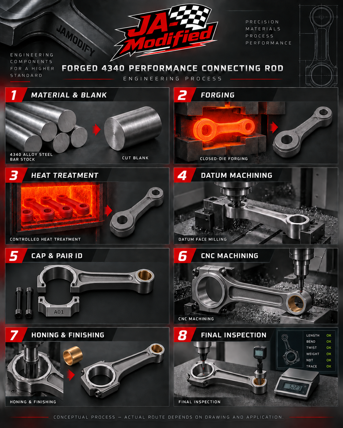
The sequence below is intentionally written as an engineering framework—not as a claim that every manufacturer uses an identical order.
Confirm engine application, target duty, center distance, bore and width geometry, bearing, pin, fastener, oiling and inspection requirements.
Verify alloy identity, material condition and batch traceability before value-adding operations begin.
Prepare the blank and heat it within the validated window required by the alloy and forging specification.
Form the near-net big end, small end and beam with controlled material flow and machining allowance.
Remove forging flash and prepare end regions only where the approved forging route calls for it.
Apply the material-specific cooling and thermal route needed to establish the required condition.
Remove scale and complete planned hardness, material and nondestructive checks before precision machining.
Create stable reference surfaces or bores that locate later operations to the approved drawing.
Rough-machine the cap zone, bolt bosses and external profile while preserving finishing allowance.
Separate the cap by the specified method and keep the rod and cap as a traceable matched pair.
Machine the approved beam, rib and clearance geometry; beam labels alone do not establish strength.
Machine the complete fastener and cap-location system, including threads, seats and locating features.
Machine the pin end and install/finish a bushing only where the drawing specifies one.
Control burrs, edges, cleanliness and intermediate dimensions throughout the machining sequence.
Reassemble the matched cap using the specified locators, fasteners, lubricant and assembly condition.
Prepare the assembled big-end bore while retaining the allowance required for final precision finishing.
Finish and verify bore size, roundness, cylindrical form and surface condition under the specified clamp state.
Apply shot peening, polishing or coating only when specified, protecting critical dimensions and defect visibility.
Verify critical geometry, bend/twist, total or end weights where required, NDT status, fasteners, cleanliness and identity.